PROJECTS
Tilt-Rotor Transition VTOL:
Team member: Akshat Verma, Rajeev Dhurandhar, Bokka Krishna Kishore, Himanshu Patil
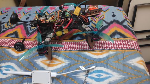
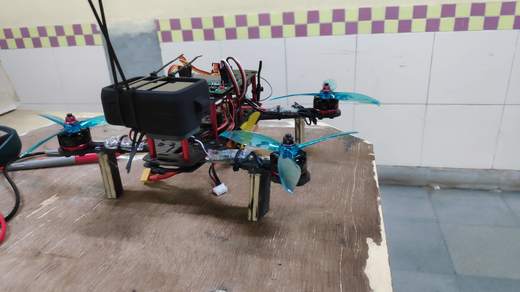
This project, in collaboration with CDS-SRG, consists of the design and build of an RC Transitioning Vertical Takeoff and Landing (VTOL) aircraft with a tilt-rotor mechanism.The aircraft takes off vertically without a need for runway following the properties of rotorcraft and then transitions to the cruise mode by tilting the front rotors forwards and follows the properties of a fixed wing UAV thereafter. Similarly, when required to land, the tilt rotors tilt upwards and the aircraft lands vertically undergoing the hover mode.
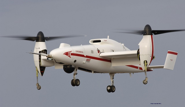
This design is motivated with an aim to bring in the contrasting advantages of the two widely used aircraft configurations- fixed wing and rotary wings. The fixed wing configuration provides energy efficiency for long and sustained flights while rotor wing configuration gives an operational capacity in a smaller workspace especially for takeoff and landing. This design brings in the best of these two worlds by switching between them appropriately.
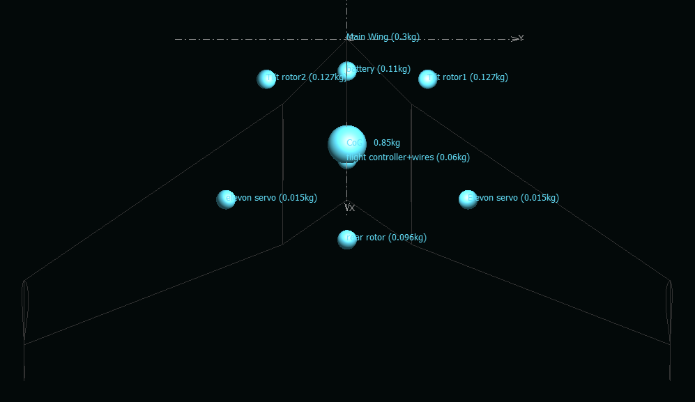
The configuration of the aircraft is similar to a tricopter with the two front rotors capable of controlled tilting and thus vectoring the thrust provided at an appropriate point of the tilt corridor.
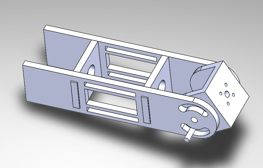
At the back, the aircraft uses a contra-rotating coaxial fan to improve yaw sensitivity . The geometric characteristics of the aircraft are similar to a flying wing with swept wings and a reflex airfoil MH45. It uses elevons as the major passive control surfaces.
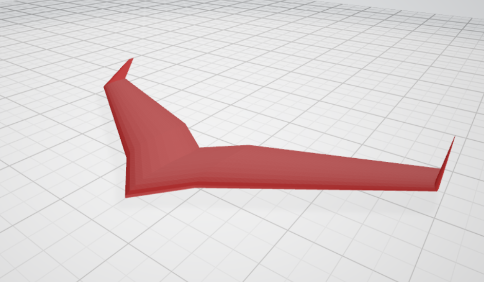
The project has involved the conceptual to detailed design of the aircraft extensively using XFLR5 for its aerodynamic analysis, the CAD modelling of the aircraft and tilt rotor mechanism and formulation and simulation of its control system using MATLAB. The team is currently working on the final stages of the project which involves its hardware build.
Launch Pad Design for Sounding Rocket:
Team Members: Akshat Verma, Ajay Tak, Piyush Porwal, Anjali AntilThis project was done as a part of the national competition Aerospanza- organised by SRM Institute of Science and Technology in sponsorship by STAR - an established startup working in space technology. Our team achieved the first-runners up position there. The project involved the design and modelling of a launch pad for a hybrid engine (solid+liquid) sounding rocket and an attempt to improve the existing launch pads aiming for mobility.


The team worked extensively on a two-degree of freedom launch pad controlled by a hydraulic linear actuator for vertical orientation and two wheels rested on a semi-circular rail for horizontal orientation. Optimised truss structures were used for the major structural components for mechanical integrity. A launch rail was designed with linear hinges using a latching mechanism for launch. The design of existing flame deflectors was also improved using multi-direction deflection. Several circuits for the launch pad avionics were formulated. For mobility, the team worked on retractable wheels. The project also included the CAD modelling of the launch pad and its mechanisms and the different components were simulated for load bearing capacity. The range of the launch was highly improved than the existing designs and was appreciated by industry professionals.


Solid Engine Model Rocket:
Team member: Akshat Verma, Rajeev Dhurandhar, Isha Mukherjee
This project was done as a part of the national competition- Synodic Rocket Design Challenge organised by the Synodic Space Settlements Pvt. Ltd which involved the design of a single-staged reusable model rocket using solid rocket boosters. Our team was placed at the second-runners up position.
The model rocket for this project was designed using the software OpenRocket aiming at maximising the apogee and the payload capacity of the rocket under the provided fuel and size constraints. The rocket weighed about 1517 gms, was 75cm long and 7cm in diameter. The achieved apogee for the rocket was around 1225m and the payload capacity was 690gms. These results were obtained after a prolonged optimisation process varying parameters like tube lengths, nose cone, material and others.


The engine of the rocket uses three clustered G77R-10 solid rocket motors. The recovery system is based on a nylon parachute with appropriate shock cords. Three trapezoidal fins have been installed for achieving longitudinal stability.
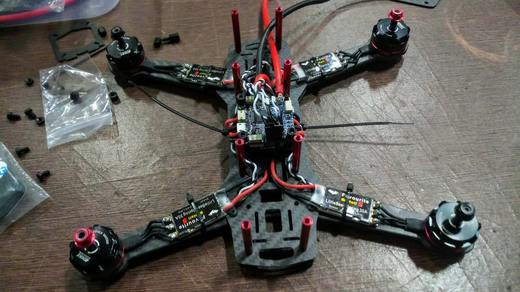
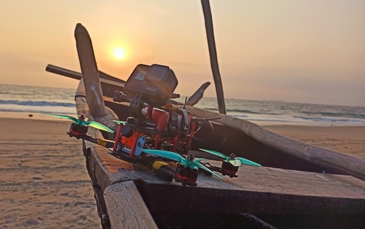
The extensive performance analysis was performed for the rocket for parameters like vertical motion profile, ground hit velocity, static margin, roll stability and drag characteristic to improve the design further.
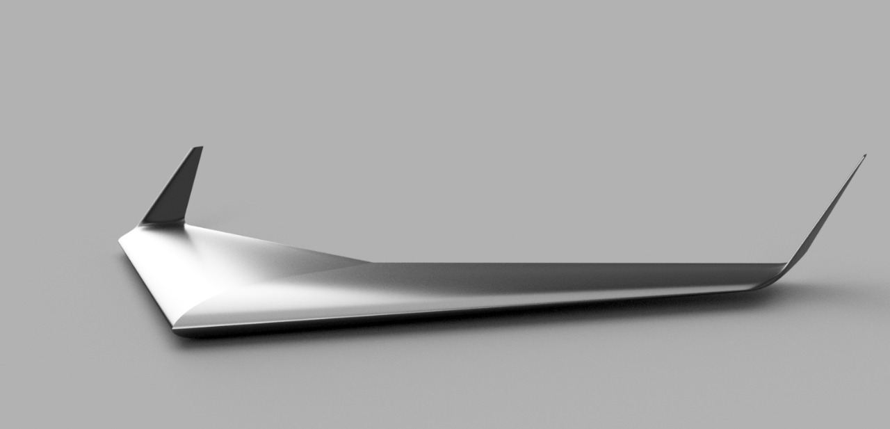
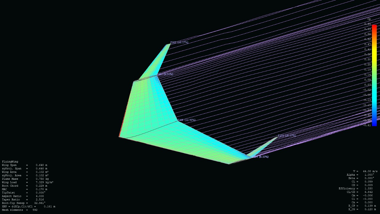
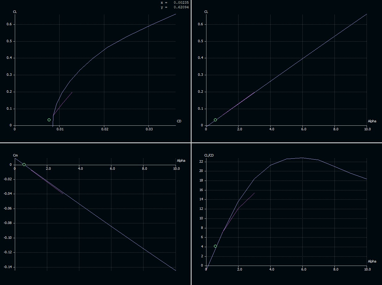
Flying Wing/ Tailless Airplane
Team member: Harshit SinghThe initial focus of the project is to learn more about the “Flying Wing” configuration of fixed wing aircrafts.This is to be done by exploring the fixed wing full scale and model aircrafts already built and understanding the pros and cons. Thereafter, to design a model of our own and manufacture it to understand how different the flight of a flying wing is in comparison to a conventional fixed wing aircraft with a tail. But most important is to have fun while exploring this new realm of aircrafts.
Boeing - IIT National Aeromodelling Competition 2021
Team-Teja members: Harshit Singh
secured a zonal second rank and won a cashprize of 25,000.
The competition requires participants to design and fabricate a glider and a catapult mechanism to launch it. Readymade models are not allowed.
Wingspan should be a maximum of 50 cm
The glider should be launched using a catapult mechanism and should not have any additional power sources
The catapult launch mechanism should be in such a way that it can independently stand on the ground. It should be a 100% mechanical device and no use of electronics/ electrical power is allowed.
The catapult should have a hold and release mechanism to launch the glider by pushing/ pulling a button/ pin etc.
Example: The participant can pull the rubber/ spring of catapult manually to “activate” the system and bring it to the “launch position” but should not continue to hold manually until release. The catapult should have a mechanism to be in “activated” state and hold the glider in launch position by itself. To launch, the participant should then push/ pull a button/ pin and the catapult should then release the glider by itself without any further manual intervention.
Launch should be done in 2 steps
Setup the glider ready for launch. In this position, the glider should be on the launcher in activated state by itself without the need for any manual intervention.
Press/ pull the mechanical button/ pin to release and launch.
The catapult should have maximum dimensions of 100 cm x 100 cm x 100 cm.


AUTONOMOUS RESCUE DRONE
Team member: Anjali Antil, Srishti Sharma, Jinay Nandu, Adithyan Rajesh, Umesh Ghaskata
The main learning objectives of the project are to make a drone autonomous, path planning, obstacles avoidance, and object detection So we will be making a drone that can be used for rescue purposes in any tragedy case ( let say earthquake). As in any disaster situation, it's difficult for humans to go inside and look for injured persons, so what we do is activate the drone from outside and it will plan its path(path planning using A* algorithm, doing its simulation in MATLAB) accordingly avoiding any danger to itself. Avoid obstacles in its path and look for humans in its path ( basically object detection) (using OpenCV) and as it finds any human it will give signals by use of a GSM module.
we have an idea to make an autonomous drone that is capable of detecting humans in disastrous conditions. This system assists in the rescue process by identifying the exact location of the survivors at the earliest. This system comprises a monitoring system along with a camera module and sensor unit to identify the existence of humans buried under the debris. The system sends the data using the GSM module ahead for further action and investigation.
Finally, the greatest advantage is they are not constrained by land-based obstacles: landscaping, trees, cars, buildings, etc. Even if constrained to predetermined flight paths, drones still have a significant speed advantage over-responding by foot. Furthermore, today’s high-resolution visible light cameras can provide extensive image detail with better stabilization than the best handheld video. Thermal cameras provide for visual detection at night, difficult weather conditions, smoke, and even some vegetation.
